
Introduction to wireless remote control of static pressure pile driver (customizable nonstandard ind
This machine iscustomized with a 100m distance. Each remote control consists of thetransmitter and the receiver. There are two output control methods: Relayoutput and RS485 output, and the rear end is connected to PLC of the controlledequipment.
Productdesign background: The static pressure pile driver is environmental pilefoundation construction equipment and vibrationless, noiseless and hydraulicpile press extractor, which has been widely used in different geologicalconditions and can be used for various piles such as U-shaped Larson steelsheet pile, Z shaped steel sheet pile, steel sheet pile and concrete pile inpebble bed and rock stratum, etc. Traditional control method mainly includeslocal panel or wired control. The wireless remote control is far away from thenearest inconvenient operation point, the actual situation of all working nodescan be viewed globally, and it can carry out judgment and alignmentsimultaneously with high accuracy, timeliness, reliability and durability, in orderto greatly improve the work efficiency and the life safety factor!
Modelis optional:
(1) DH-Z1Y5S28F1X5D, operating voltage of receiver endDC24V;
(2)DH-Z1Y5S28F1X5D485,operating voltage of receiver end DC24V;
Designspecification of wireless remote control of static pressure pile driver(customizable nonstandard industrial remote control)
1.Standard configuration of remote control: 1 transmitter, 1 receiver;
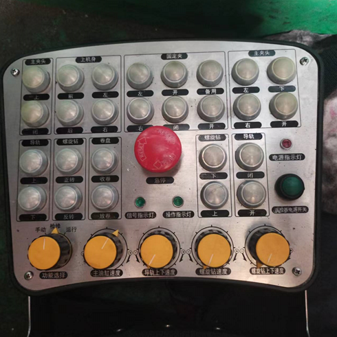
2.Layout of transmitter: 1 three-position self-locking hold rotary switch; 45-position band switches; 27 buttons; 1 signal LED light + 1 LED operationlight+ 1 LED power light; the start + emergency stop buttons are used to startthe remote control system and close and power on the main relay, and cut offthe remote control system and disconnect the main relay in case of emergenciesto control the controlled equipment.
3.Output method (1) is optional:
27buttons correspond to 27 normally open relay outputs; three-position rotaryswitches correspond to 3 normally open relay outputs; 5-position band switchescorrespond to 4 normally open relay outputs, start + emergency stop buttonsjointly correspond 1 switching value output, switching value actions correspondto passive dry contact relay outputs, the contact capacity is 250V/10A, and thedirect current is 30V/5A. This machine outputs a total of 52 switching values.
Outputmethod (2) is optional:
RS485interface output can be determined by both parties according to the Moudbuscommunication protocol to be proposed and value definition details; start +emergency stop buttons jointly correspond 1 switching value output, switchingvalue actions correspond to passive dry contact relay outputs, the contactcapacity is 250V/10A, and the direct current is 30V/5A.
4.Function execution:
1)27 buttons are designed as inching type but without interlock logic forrear-end PLC customization. There are four rows of characters corresponding tothe buttons, with 16 characters in the upper two rows and 11 characters in thelower two rows:
Onthe chuck, in front of the upper body, on the left of the upper body, on theleft of the clip, open clip, standby, on the left of the main chuck, below themain chuck, closed clip, behind the upper body, on the right of the upper body,on the right of the clip, closed clip, open clip, on the right of the mainchuck, open main chuck, on the guide rail, forward rotation of twist drill,winch winding, below the twist drill, closed guide rail, below the guide rail,backward rotation of twist drill, winch winding, on the twist drill, open guiderail and power switch of remote control.
2)1 three-position rotary switch, self-locking hold mode, corresponding functions(manual, overhaul and operation), corresponding to 3 normally open relayoutputs at the receiver end.
4)4 5- position band switches, including speed of master cylinder, up and downspeed of guide rail, speed of twist drill, and up and down speed of twistdrill. At rotate speed 1, relay 1 is closed. At rotate speed 2, relays 1 and 2are closed. At rotate speed 3, relays 1, 2 and 3 are closed, and so on. Atrotate speed 5, relays 1, 2, 3, 4 and 5 are closed, corresponding to 5 normallyopen relay outputs;
5)Three LED lights, of which the first is used to indicate the power supply ofthe transmitter; when the second is used to display the actuating signal, thegreen light flickers; when the third is used to display the operation light andthe transmitter is operated, the green light flickers.
6)Start + emergency stop buttons. After the buttons are turned on, thetransmitter starts to supply power, the main relay at the receiver end isclosed and powered on, and the main power of the controlled end is connected;when the emergency stop button is pressed, the transmitter is turned off. Atthis moment, all output circuits of corresponding receivers are disconnected,and PLC of the controlled end is disconnected to ensure the equipment is instandby state.
5.Anti- disturbance performance: Automatic frequency hopping is adopted. In caseof same frequency interference, it can automatically search an idle frequencyand automatically skip to this idle frequency, the receiving and transmittingends will skip simultaneously and cannot work at the fixed frequency point andthe hopping difference is at a millisecond class to avoid various interferencesources and same frequency interference of site.
6. Code matching: To configureor replace or start the emergency transmitter or receiver, code matching methodis adopted. Two or three or four buttons of the transmitter are pressedsimultaneously for a certain time to match the codes.
7.Each set of address codes is unique: There is a unique signal encrypted codebetween the transmitter and the receiver of each remote control to ensure nointerference of several sets in the same environment. The transmitter and thereceiver use the same wireless frequency point to ensure the unique targetedtransmitting and receiving signal.
8.The transmitter can be powered by 1 lithium battery for consecutive 1/3 months,and the receiver can be powered by DC12V and DC24V.
9.5A or 10A fuse is used to protect the overcurrent protection receiver fromburn;
Productdesign drawing:
;)
;)